 |
| Image formation in a TEM and SEM |
|
Film of hooikoort.tv about the laser and the electronmicroscope of GI in Nijmegen | |
Electron microscopy (EM) is basically utilized to study structures which are unvisible to the naked eye, or are too small to be well revealed with a light microscope.
The two main types of EM techniques are
Transmission Electron Microscopy (TEM) and
Scanning Electron Microscopy (SEM). In the introduction on
electron microscopy we saw that TEM and SEM produce different kind of images:roughly speaking respectively cross-views of the object (TEM) or images of the surface of the object (SEM). Although both technique involve electrons to produce enlarged images they work according to different principles.
The mechanism behind TEM and SEM are briefly commented here below:
| Principle of Transmission & Scanning Electron Microscopy |
| Transmission Electron Microscope (TEM) | Scanning Electron Microscope (SEM) |
 |  |
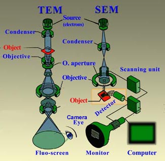
How is an magnified image of an object created in a TEM?
In a TEM the object (for example a cluster of cells) is usually previously cut in very thin sections (ultrasection <100nm) and pre-treated with heavy metals which by preference bind ("stain") to certain characteristic structures, like membranes, proteins and DNA (see preparation TEM). Sometimes the objects (e.g. virussen or polymeric aggregates) are thin enough to be partly permeant to the electron beam. In such cases hardly any pretreatment is necessary. Once in the TEM the object is bombarded by a beam of electrons,the so-called primary electrons. In areas in the object where these electrons encounter atoms with a large (heavy) atomic nucleus (e.g. the nuclei of the heavy metals of the pretreatment), they rebound. Electrons are also repulsed (or absorbed) in areas where the material is relatively condense or thick. However, in regions where the material consists of lighter atoms or where the specimen is thinner or less concentrated, the electron are able to pass through. Eventually the traversing electrons (transmission) reach the scintillator plate at the base of the column of the microscope. The scintillator contains material (e.g. phosphor compounds) that can absorb the energy ot the strucking incoming electrons and convert it to light flashes. The contrasted image that is formed on this plate corresponds with the selective pattern of reflection or permission of electrons, depending on the local properties of the object. Thus, one can see for example where cytoskeletal elements and membranes are located because the corresponding area remain dark,whereas the cytosol around these structures appears as light (see example; G= Golgi, AF = Actin filaments, Mt = Mitochondrion). In practice the bombarding electrons are focussed to a bundle onto the object. The fine pattern of exiting electrons leaving the object is then greatly enlarged by electromagnetic lenses: a many times enlarged projection image is the result. |
In SEM the object is bombarded by primary electrons from the source according to a scanning pattern. These strucking electrons cause the emission of secondary electrons (to some extend one could compare the effect with that of a pool balls, in which the striking balls pushes the receptive one away). In SEM an image of the surface of the object is made. The height and slope of the surface of the object in a particular area co-determines the number of generated secondary electrons per time unit and the velocity of those electrons. The secondary electrons are attracted by the Corona and strike the a scintillator disc. Like in the TEM, this disc contains sun=bstances which can convert the energy of the striking electrons into photons (light). The more secondary electrons reach the scintillator, the brighter the signal is at that point. This luminescence signal is further amplified by a photomultiplier tube and transduced to a video signal that is fed to a cathode ray tube in synchrony with the scan movement of the electron beam. Nowadays the analog image is converted to a monochromatic (gray shades) computer image that can be further digitally processed. The intensity pattern in the final image reflects the levels in the sample and looks like a shadow-cast view (see an Ambrosia pollen grain as an example).
In Cryo-SEM microscopes frozen material, e.g. cells, can be fractured in order to obtain a view of the surface of the structures inside the broken volume. In microscopes equipped with EDS (Energy Dispersed Spectroscopy) or EDAX (Energy-Dispersed Analysis of X-rays) detectors which collect the energy of directly reflected electrons (back scattered electrons) and X-ray, it is possible to map which lements are present in the outermost surface layer.
|
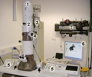 |  |
Transmission Electron Microscope (TEM)
1: Electron cannon in the upper part of the column. 2 Electro-magnetic lenses to direct and focus the electron beam inside the column. 3: Vacuum pumps system. 4: Opening to insert a grid with samples into the high-vacuum chamber for observation. 5: Operation panels (left for alignment; right for magnification and focussing; arrows for positioning the object inside the chamber). 6: Screen for menu and image display. 7: Water supply to cool the instrument. |
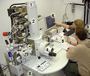
Scanning Electron Microscope (SEM)
1: Electron cannon in the upper part of the column (here a so-called field-emission source). 2 Electro-magnetic lenses to direct and focus the electron beam inside the column. 3: Vacuum pumps system. 4: Opening to insert the object into the high-vacuum observation chamber in conventional SEM mode. 5: Operation panel with focus, alignment and magnification tools and a joystick for positioning of the sample. 6: Screen for menu and image display. 7: Cryo-unit to prepare (break, coat and sublimate) frozen material before insertion in the observation chamber in Cryo-SEM mode. 8: Electronics stored in cupboards under the desk. 9: Technicians Mieke Wolters-Arts and Geert-Jan Janssen discussing a view. |


